Joined: Tue Oct 11 2005, 01:33AM
Location: Calgary, Alberta
Posts: 5893
65Coronet7165 wrote ... ... I wanted to install everything so that I took the power for the headlamps directly from the alternator instead of the battery (which Daniel recommends for older Mopars).
The "custom harness" he supplied was designed to use the battery as a power source, however, instead of the alternator. We modified it to suit our needs by lengthening the ground wire (so it would reach back to the battery) and the "trigger" wires so they would reach and connect into the original harness at the driver's side low beam connector.
Once all was assembled, the results are quite good!! The headlights are VERY bright, no matter if the car is at idle or tooling down the road ...
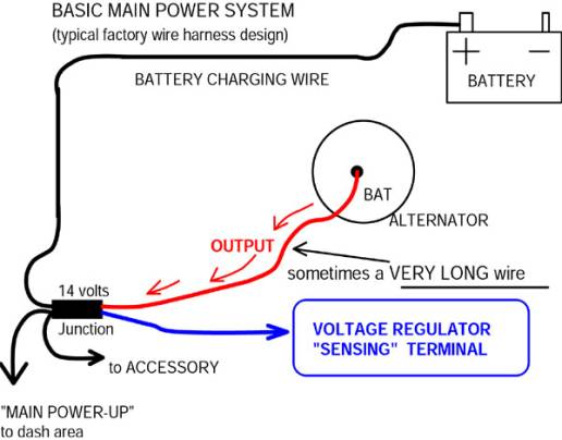
If you look at one of MAD's disgrams
Note the "long" wire from the alternator to the main splice and the "charge" wire from the splice to the battery. Note also the regulator does its voltage monitoring at the splice not at the battery or the alternator. In normal operation, the voltage regulator will attemp to maintain a voltage of about 14v at the splice. So if the accessory current load is high there will be a voltage drop across the wire from the alternator and the splice. For example if the voltage drop is 2 volts, then 14v at the splice plus 2 volts across the wire means the alternator is putting out 16v. I suggest that is why your lights are as you say "VERY bright" and I further suggest you buy lots of spare bulbs since they don't last long at 16v.
The proper place to attach all "options" is at the splice. However this just adds to the bulkhead problem. So if you don't do the MAD bulkhead bypass then your headlights should run to the battery. They won't see the regulated 14v, they will see closer to 12.5v or 13v - but they will last a lot longer.
When making wiring changes to cars, two things you must be very aware of, great ground connections and how much voltage drop you are getting.
Joined: Sun Feb 26 2006, 08:46PM
Location: Kingston,Ontario
Posts: 5622
To keep things "positive" I stay "grounded" I am a "discharge" of information on 67/68 Chryslers Hope you get a "charge" outa this and not find it "revolting" Shocked yet??
Joined: Mon Feb 13 2006, 12:39AM
Location: Fresno, CA
Posts: 516
65Coronet7165 wrote ... Well, I've got a fairly new 60 amp Chrysler alternator and a Petronix electronic voltage regulator that's in a case that looks like the original points reg. Drove again today and didn't get any large discharge readings......I was driving along at about 25 mph though...not idling in drive as I was yesterday. I'll have to check this out further.
Cbarge, I've been hoping to avoid doing the MAD upgrade. That was the primary reason for originally considering Daniel Stern's lighting relays and upgraded wiring. I was hoping to save the alternator gauge and my toggle headlight switch by taking the major load off of them...
I'm not real confident about going in and changing the wiring around on the car. Daniel supplied a ready made harness which we had to modify slightly (and that much was within my comfort zone as far as wiring goes). If MAD offered a harness or something a bit easier to understand I'd go for it.
If you have any suggestions or if you could post some instructions I'd be happy to reconsider.
Even though I have not yet installed the relays I bought from MAD Electrical for the lamps on Chaz, I HAVE already done the Ammeter bypass since I found this at the bulkhead connectors;
These are the connectors that are the positive feed to the ammeter from the engine bay. There was enough resistance to cook the male blade and the surrounding connector housing at the bulkhead.
I had already upgraded to electronic ignition and bought an electronic voltage regulator off EBay (pretty much the same thing as what Lea shows) so the charging system would not have spikes due to the mechanical points in the stock Voltage Regulator in addition to upgrading to a 60A "square-back" alternator and having a parallel output to the starter relay positive terminal, but I might not have done those things in time to prevent the damage that you see here.
I no longer have a working ammeter, but that is OK for now, because I won't have to worry about a fire starting at the bulkhead connector. So don't worry about saving the ammeter, protect the rest of your 300 first! !thumb
I've got a spare ammeter I would be willing to give you, should you need it. I hope to have the ammeter in my dash converted to a voltmeter when I get the opportunity to have the instrument cluster rebuilt.
Joined: Fri Dec 22 2006, 08:41PM
Location: Warrenton, Virginia
Posts: 1366
Thanks all, and this is an interesting and FUNNY thread !clown
Yeah, I'm trying to stay positive and charged up about this whole subject. I want to prevent a "meltdown" at all costs.
Seriously, I went to bed early last night and woke up thinking about this (which I probably should have done before I started). Electricity, like water, is going to take the path of least resistance. Since I wired my relays directly to the alternator output I've effectively bypassed the regulator (right?). When the headlights are switched "ON", the current is being sent thru the relays to the lights and then back to the battery thru the ground. Since the voltage regulator is not on this "path", would my alternator be overcharging the battery??? AND, because this is the least resistant path and my headlights are really being "juiced" they will heat up more than they should (and H1 bulbs run HOT anyway) maybe the headlight housing itself will get too hot causing other problems.
Anyway, hope you all are as "juiced" up as I am this morning! !drive !police
Joined: Tue Oct 11 2005, 01:33AM
Location: Calgary, Alberta
Posts: 5893
A little story. You have a small pond in your front yard with a little fountain in the middle. For the fountain to look right the water coming out of the garden hose must be at 12 psi. The garden house runs all the way around you house to the backyard where you have a well and a pump. After a lot of running back and forth you get the pump speed adjusted just right and the fountain runs happily at 12 psi. So you sit on the front porch with a beer and admire your handy work.
However you notice that every time the sun goes behind some clouds, the garden hose contracts and your fountain water shoots too high. Not wanting to run back and forth to keep adjusting the pump, you tap into the hose beside the porch to add a sensor that will allow you to monitor the pressure. You rig a long string to the pump throttle. This works but you have stay on the porch holding the string. Unfortunately you need another beer and a pit stop. A buddy drives up and you convince him to hold the string while you get the beer.
Fortunately your buddy is an electronics nut so he builds you a little box which will automatically adjust the pump no matter how much the hose shrinks or expands in the sun. All is great, you and your buddy sit on the porch with your beers and admire your fountain work automatically.
You notice that the pressure gauge on the little black box reads 14 psi, but your buddy says that's ok; it just means there are 2 psi lost because of water drag in the hose between the black box and the fountain. You remember that you used a 25' hose between the black box and the fountain. You also remember that you couldn't find a shorter hose to run from the black box back to the pump so you grabbed a 100' length and coiled the excess by the pump. So you do a bit of math, since 25' drops the pressure by 2 psi, then 100' will drop it 8 psi more. Adding up the losses you come to the conclusion that the pressure at the pump must be 12 + 2 + 8 = 22 psi Since the capacity of the pump is only 19 psi, the pump is overheating. So you replace the 100' of hose with a 50' length and the pump pressure drops to 18 psi making the pump happy.
Ok enough plumbing, you've figured out I'm sure that the pump is your alternator, the black box is your voltage regulator and the fountain is your battery. You should also have some understanding that as the load on the system varies, the regulator will drive the alternator as hard as need be to maintain the voltage at its measuring point to be 14v.
However there is a catch, isn't there always! The wire between the splice where the regulator maintains its 14v and the battery is not ordinary wire, its resistance wire. The extra resistance in this wire causes a greater voltage drop as the current increases. If your battery is low on charge and is sitting at say 9v, trying to charge it with 12v would cause it to overheat and buckle the plates. So careful selection of wire resistance allows the system to drop extra volts across the charge wire. Cool, the splice sits locked at 14v, the battery starts off with a charging voltage of around 10v and this charging voltage slowly increases as the battery charges and draws less current. When the battery is finally fully charged and it's current draw drops to zero, it will read a maximum of 14v.
So what, well it means every time you start your engine, you drain the battery a little bit and the alternator supplies current to the battery to recharge it. It also means the voltage at the battery will be lower after a start and will gradually increase as the battery charges. A very nice but carefully balanced system to charge your battery without over charging it.
The kicker, ready for it! Your battery and it's associated charging wire circuit are designed to be used ONLY TO START THE CAR. All accessories, lights, whatever are assumed to be connected to the master splice where the voltage is regulated to 14v.
So if you attach some load directly to the battery, the charging current from the alternator will be partially re-routed - some to the load and the rest to charge the battery. BUT this means your battery will NEVER reach full charge while the extra load is drawing power. So you guys with your electronic ignition boxes wired directly to the battery are fooling yourselves.
If you look at the other end, the voltage at the alternator will ALWAYS be higher than 14v UNLESS the current load is zero. Because accessory load and periodic battery charging will cause the current drawn to jump around, you must expect wide fluctuations in the voltage. Not a real good place to connect anything.
One last point, what happens when you upgrade from a 30 amp alternator to a 120 amp? Well, since the battery is unchanged, the charging wire between the battery and the splice is fine. However, the wire between the alternator and the splice MUST BE CHANGED. The stock wire will handle 30 amps plus some safety factor, try to push 120 amps through it and you will see smoke.
So there you are, no mystery, just common sense! !thumb !thumb
Joined: Fri Dec 22 2006, 08:41PM
Location: Warrenton, Virginia
Posts: 1366
OK Bill, a nice parable to be sure... but I'm sorry to say you lost me a bit. I've got the lights hooked up to the alt for power source, will it HURT anything??? Seems to me there is UN-regulated current going thru the lighting circuit now.....how does this affect the rest of the system?? The alternator output is now connected to 2 paths, the "normal" one and the one that feeds the headlights.
Sorry, but I am an ammeter for certain!!
I love this site though, you guys are the greatest and frankly, I don't know what I'd do without your input and advice !thumb
Joined: Tue Oct 11 2005, 01:33AM
Location: Calgary, Alberta
Posts: 5893
65Coronet7165 wrote ... ... I've got the lights hooked up to the alt for power source, will it HURT anything??? Seems to me there is UN-regulated current going thru the lighting circuit now.....how does this affect the rest of the system?? The alternator output is now connected to 2 paths, the "normal" one and the one that feeds the headlights...
Ok the only place on your whole car that has regulated voltage is the splice where the sense wire from the regulator connects. If the voltage at the splice is locked to 14v by the regulator then you know the voltage at the alternator will always be higher and will bounce up and down as you use accessories.
For example, when you use your turn signals the lights go on and off which will raise and lower the current draw from the alternator. The alternator will raise and lower it's output voltage to do this. So if your headlights are connected at the alternator their brightness will slightly pulse in time with your turn signals. If your battery is a little run down, the alternator will raise its voltage to accommodate the charging current and you headlights will get VERY bright and VERY hot.
For those reading and thinking wait a darn minute, doesn't the battery supply the current and all the alternator does is charge the battery. Wrong !!
Think about it, the voltage at the splice is locked to 14v and the battery will always be equal or lower in voltage. Current always flows from higher to lower potentials. I can only think of three instances where current flows out of the battery, when starting the engine, running accessories when the engine is stopped or if you add enough accessories that the current draw exceeds the ability of the alternator.
SO ALL ACCESSORIES MUST BE CONNECTED AT THE SPLICE!!!